×
![]()
graphdraw-mainerd: Instance-to-Instance Comparison Results
| Type: | Instance |
| Submitter: | Cézar Augusto Nascimento e Silva |
| Description: | In the Graph Drawing problem a set of symbols must be placed in a plane and their connections routed. The objective is to produce aesthetically pleasant, easy to read diagrams. As a primary concern one usually tries to minimize edges crossing, edges' length, waste of space and number of bents in the connections. When formulated with these constraints the problem becomes NP-Hard . In practice many additional complicating requirements can be included, such as non-uniform sizes for symbols. Thus, some heuristics such as the generalized force-direct method and Simulated Annealing have been proposed to tackle this problem. uses a grid structure to approach the Entity-Relationship (ER) drawing problem, emphasizing the differences between ER drawing and the more classical circuit drawing problems. presented different ways of producing graph layouts (e.g.: tree, orthogonal, visibility representations, hierarchic, among others) for general graphs with applications on different subjects. The ability to automatically produce high quality layouts is very important in many applications, one of these is Software Engineering: the availability of easy to understand ER diagrams, for instance, can improve the time needed for developers to master database models and increase their productivity. Our solution approach involves two phases: (\\(i\\)) firstly the optimal placement of entities is solved, i.e.: entities are positioned so as to minimize the distances between connected entities; and (\\(ii\\)) secondly, edges are routed minimizing bends and avoiding the inclusion of connectors too close. We present the model for the first phase of our problem. |
| MIPLIB Entry |
Parent Instance (graphdraw-mainerd)
All other instances below were be compared against this "query" instance.  |
 |
 |
 |
 |
 |
|
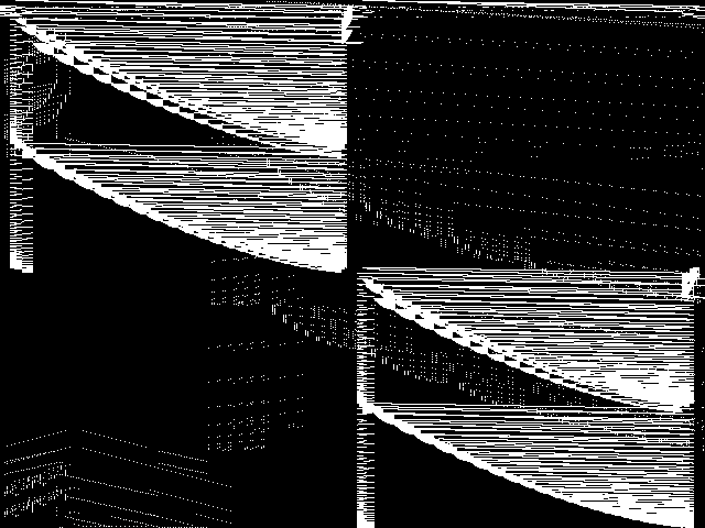
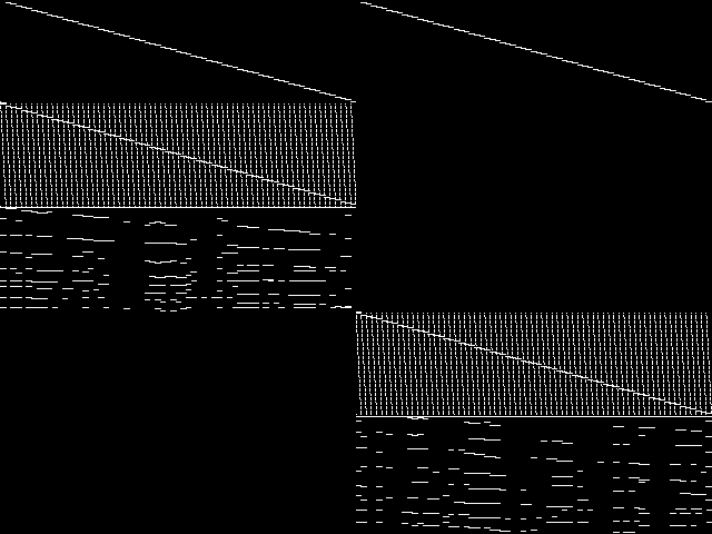
Raw
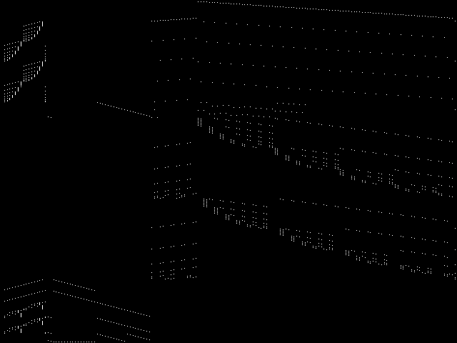
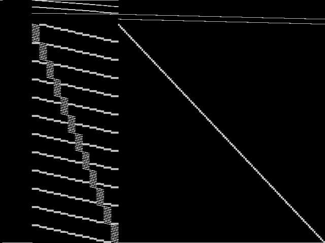
This is the CCM image before the decomposition procedure has been applied.
|
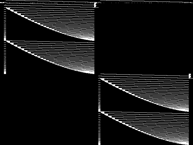
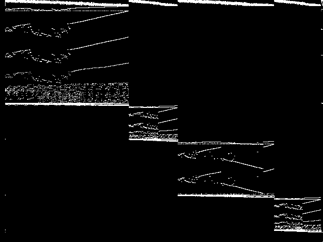
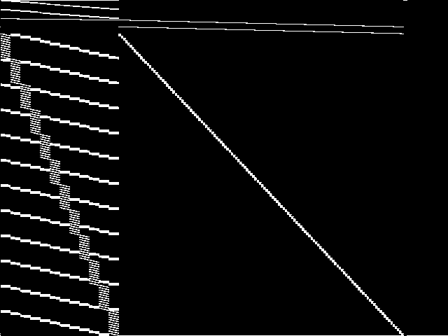
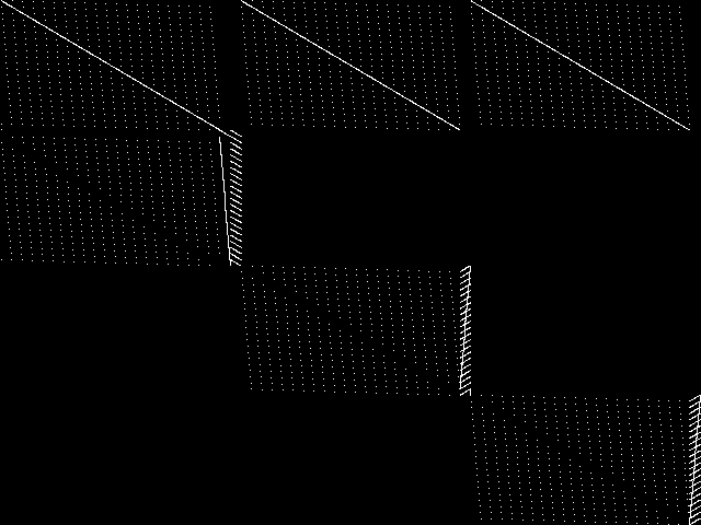
Decomposed
This is the CCM image after a decomposition procedure has been applied. This is the image used by the MIC's image-based comparisons for this query instance.
|
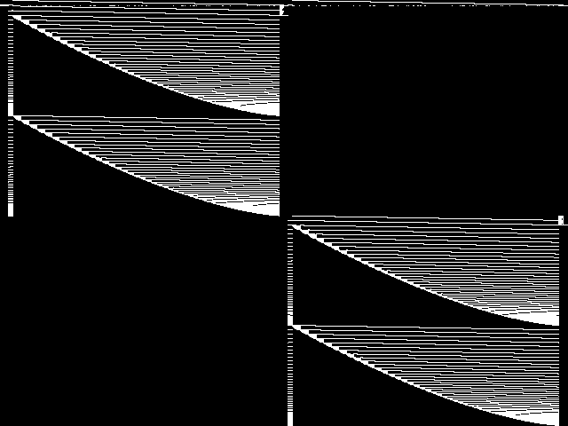
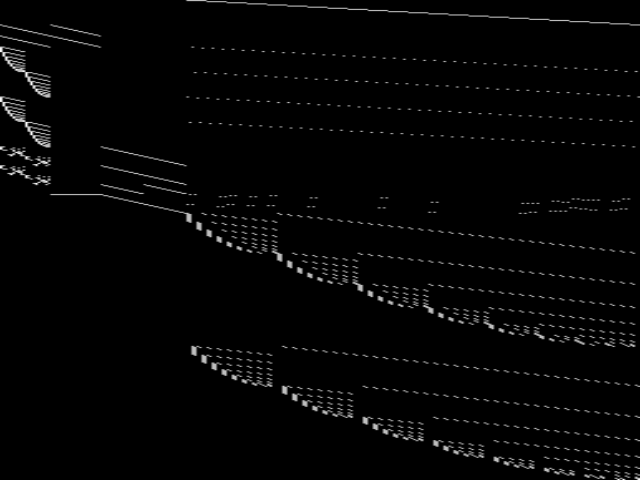
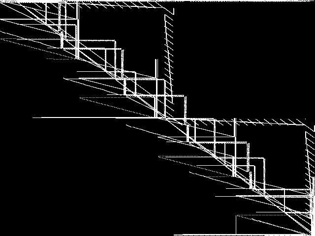
Composite of MIC Top 5
Composite of the five decomposed CCM images from the MIC Top 5.
|
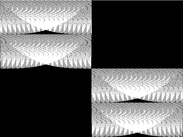
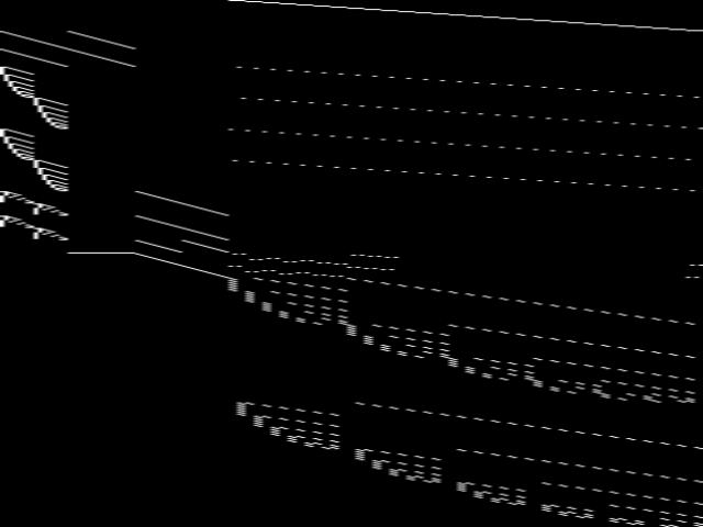
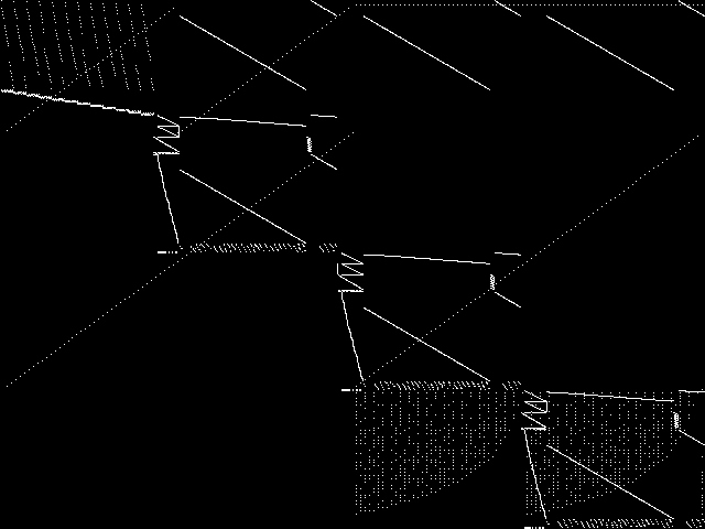
Composite of MIPLIB Top 5
Composite of the five decomposed CCM images from the MIPLIB Top 5.
|
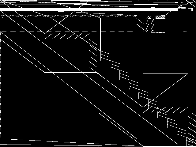
Model Group Composite Image
Composite of the decomposed CCM images for every instance in the same model group as this query.
|
MIC Top 5 Instances
These are the 5 decomposed CCM images that are most similar to decomposed CCM image for the the query instance, according to the ISS metric. |
Decomposed
These decomposed images were created by GCG.
|
 |
 |
 |
 |
 |
| Name | graphdraw-opmanager [MIPLIB] | graphdraw-grafo2 [MIPLIB] | wnq-n100-mw99-14 [MIPLIB] | neos-820879 [MIPLIB] | supportcase12 [MIPLIB] | |
|
Rank / ISS
The image-based structural similarity (ISS) metric measures the Euclidean distance between the image-based feature vectors for the query instance and all other instances. A smaller ISS value indicates greater similarity.
|
1 / 0.663 | 2 / 0.784 | 3 / 1.182 | 4 / 1.262 | 5 / 1.337 | |
|
Raw
These images represent the CCM images in their raw forms (before any decomposition was applied) for the MIC top 5.
|
 |
 |
 |
 |
 |
MIPLIB Top 5 Instances
These are the 5 instances that are most closely related to the query instance, according to the instance statistic-based similarity measure employed by MIPLIB 2017 |
Decomposed
These decomposed images were created by GCG.
|
 |
 |
 |
 |
 |
| Name | graphdraw-opmanager [MIPLIB] | graphdraw-grafo2 [MIPLIB] | graphdraw-domain [MIPLIB] | graphdraw-gemcutter [MIPLIB] | neos-3402294-bobin [MIPLIB] | |
|
Rank / ISS
The image-based structural similarity (ISS) metric measures the Euclidean distance between the image-based feature vectors for the query instance and all model groups. A smaller ISS value indicates greater similarity.
|
1 / 0.663 | 2 / 0.784 | 325 / 1.843 | 358 / 1.853 | 859 / 2.209 | |
|
Raw
These images represent the CCM images in their raw forms (before any decomposition was applied) for the MIPLIB top 5.
|
|
|
 |
 |
 |
Instance Summary
The table below contains summary information for graphdraw-mainerd, the five most similar instances to graphdraw-mainerd according to the MIC, and the five most similar instances to graphdraw-mainerd according to MIPLIB 2017.
| INSTANCE | SUBMITTER | DESCRIPTION | ISS | RANK | |
|---|---|---|---|---|---|
| Parent Instance | graphdraw-mainerd [MIPLIB] | Cézar Augusto Nascimento e Silva | In the Graph Drawing problem a set of symbols must be placed in a plane and their connections routed. The objective is to produce aesthetically pleasant, easy to read diagrams. As a primary concern one usually tries to minimize edges crossing, edges' length, waste of space and number of bents in the connections. When formulated with these constraints the problem becomes NP-Hard . In practice many additional complicating requirements can be included, such as non-uniform sizes for symbols. Thus, some heuristics such as the generalized force-direct method and Simulated Annealing have been proposed to tackle this problem. uses a grid structure to approach the Entity-Relationship (ER) drawing problem, emphasizing the differences between ER drawing and the more classical circuit drawing problems. presented different ways of producing graph layouts (e.g.: tree, orthogonal, visibility representations, hierarchic, among others) for general graphs with applications on different subjects. The ability to automatically produce high quality layouts is very important in many applications, one of these is Software Engineering: the availability of easy to understand ER diagrams, for instance, can improve the time needed for developers to master database models and increase their productivity. Our solution approach involves two phases: (\\(i\\)) firstly the optimal placement of entities is solved, i.e.: entities are positioned so as to minimize the distances between connected entities; and (\\(ii\\)) secondly, edges are routed minimizing bends and avoiding the inclusion of connectors too close. We present the model for the first phase of our problem. | 0.000000 | - |
| MIC Top 5 | graphdraw-opmanager [MIPLIB] | Cézar Augusto Nascimento e Silva | In the Graph Drawing problem a set of symbols must be placed in a plane and their connections routed. The objective is to produce aesthetically pleasant, easy to read diagrams. As a primary concern one usually tries to minimize edges crossing, edges' length, waste of space and number of bents in the connections. When formulated with these constraints the problem becomes NP-Hard . In practice many additional complicating requirements can be included, such as non-uniform sizes for symbols. Thus, some heuristics such as the generalized force-direct method and Simulated Annealing have been proposed to tackle this problem. uses a grid structure to approach the Entity-Relationship (ER) drawing problem, emphasizing the differences between ER drawing and the more classical circuit drawing problems. presented different ways of producing graph layouts (e.g.: tree, orthogonal, visibility representations, hierarchic, among others) for general graphs with applications on different subjects. The ability to automatically produce high quality layouts is very important in many applications, one of these is Software Engineering: the availability of easy to understand ER diagrams, for instance, can improve the time needed for developers to master database models and increase their productivity. Our solution approach involves two phases: (\\(i\\)) firstly the optimal placement of entities is solved, i.e.: entities are positioned so as to minimize the distances between connected entities; and (\\(ii\\)) secondly, edges are routed minimizing bends and avoiding the inclusion of connectors too close. We present the model for the first phase of our problem. | 0.663317 | 1 |
| graphdraw-grafo2 [MIPLIB] | Cézar Augusto Nascimento e Silva | In the Graph Drawing problem a set of symbols must be placed in a plane and their connections routed. The objective is to produce aesthetically pleasant, easy to read diagrams. As a primary concern one usually tries to minimize edges crossing, edges' length, waste of space and number of bents in the connections. When formulated with these constraints the problem becomes NP-Hard . In practice many additional complicating requirements can be included, such as non-uniform sizes for symbols. Thus, some heuristics such as the generalized force-direct method and Simulated Annealing have been proposed to tackle this problem. uses a grid structure to approach the Entity-Relationship (ER) drawing problem, emphasizing the differences between ER drawing and the more classical circuit drawing problems. presented different ways of producing graph layouts (e.g.: tree, orthogonal, visibility representations, hierarchic, among others) for general graphs with applications on different subjects. The ability to automatically produce high quality layouts is very important in many applications, one of these is Software Engineering: the availability of easy to understand ER diagrams, for instance, can improve the time needed for developers to master database models and increase their productivity. Our solution approach involves two phases: (\\(i\\)) firstly the optimal placement of entities is solved, i.e.: entities are positioned so as to minimize the distances between connected entities; and (\\(ii\\)) secondly, edges are routed minimizing bends and avoiding the inclusion of connectors too close. We present the model for the first phase of our problem. | 0.783720 | 2 | |
| wnq-n100-mw99-14 [MIPLIB] | M. Winkler | Weighted n-queens problem with an additional separation constraint. Solved by Gurobi 4.6.1 (12 threads) in 28124 seconds (January 2012). | 1.182382 | 3 | |
| neos-820879 [MIPLIB] | NEOS Server Submission | Imported from the MIPLIB2010 submissions. | 1.261913 | 4 | |
| supportcase12 [MIPLIB] | Michael Winkler | MIP instances collected from Gurobi forum with unknown application | 1.337142 | 5 | |
| MIPLIB Top 5 | graphdraw-opmanager [MIPLIB] | Cézar Augusto Nascimento e Silva | In the Graph Drawing problem a set of symbols must be placed in a plane and their connections routed. The objective is to produce aesthetically pleasant, easy to read diagrams. As a primary concern one usually tries to minimize edges crossing, edges' length, waste of space and number of bents in the connections. When formulated with these constraints the problem becomes NP-Hard . In practice many additional complicating requirements can be included, such as non-uniform sizes for symbols. Thus, some heuristics such as the generalized force-direct method and Simulated Annealing have been proposed to tackle this problem. uses a grid structure to approach the Entity-Relationship (ER) drawing problem, emphasizing the differences between ER drawing and the more classical circuit drawing problems. presented different ways of producing graph layouts (e.g.: tree, orthogonal, visibility representations, hierarchic, among others) for general graphs with applications on different subjects. The ability to automatically produce high quality layouts is very important in many applications, one of these is Software Engineering: the availability of easy to understand ER diagrams, for instance, can improve the time needed for developers to master database models and increase their productivity. Our solution approach involves two phases: (\\(i\\)) firstly the optimal placement of entities is solved, i.e.: entities are positioned so as to minimize the distances between connected entities; and (\\(ii\\)) secondly, edges are routed minimizing bends and avoiding the inclusion of connectors too close. We present the model for the first phase of our problem. | 0.663317 | 1 |
| graphdraw-grafo2 [MIPLIB] | Cézar Augusto Nascimento e Silva | In the Graph Drawing problem a set of symbols must be placed in a plane and their connections routed. The objective is to produce aesthetically pleasant, easy to read diagrams. As a primary concern one usually tries to minimize edges crossing, edges' length, waste of space and number of bents in the connections. When formulated with these constraints the problem becomes NP-Hard . In practice many additional complicating requirements can be included, such as non-uniform sizes for symbols. Thus, some heuristics such as the generalized force-direct method and Simulated Annealing have been proposed to tackle this problem. uses a grid structure to approach the Entity-Relationship (ER) drawing problem, emphasizing the differences between ER drawing and the more classical circuit drawing problems. presented different ways of producing graph layouts (e.g.: tree, orthogonal, visibility representations, hierarchic, among others) for general graphs with applications on different subjects. The ability to automatically produce high quality layouts is very important in many applications, one of these is Software Engineering: the availability of easy to understand ER diagrams, for instance, can improve the time needed for developers to master database models and increase their productivity. Our solution approach involves two phases: (\\(i\\)) firstly the optimal placement of entities is solved, i.e.: entities are positioned so as to minimize the distances between connected entities; and (\\(ii\\)) secondly, edges are routed minimizing bends and avoiding the inclusion of connectors too close. We present the model for the first phase of our problem. | 0.783720 | 2 | |
| graphdraw-domain [MIPLIB] | Cézar Augusto Nascimento e Silva | In the Graph Drawing problem a set of symbols must be placed in a plane and their connections routed. The objective is to produce aesthetically pleasant, easy to read diagrams. As a primary concern one usually tries to minimize edges crossing, edges' length, waste of space and number of bents in the connections. When formulated with these constraints the problem becomes NP-Hard . In practice many additional complicating requirements can be included, such as non-uniform sizes for symbols. Thus, some heuristics such as the generalized force-direct method and Simulated Annealing have been proposed to tackle this problem. uses a grid structure to approach the Entity-Relationship (ER) drawing problem, emphasizing the differences between ER drawing and the more classical circuit drawing problems. presented different ways of producing graph layouts (e.g.: tree, orthogonal, visibility representations, hierarchic, among others) for general graphs with applications on different subjects. The ability to automatically produce high quality layouts is very important in many applications, one of these is Software Engineering: the availability of easy to understand ER diagrams, for instance, can improve the time needed for developers to master database models and increase their productivity. Our solution approach involves two phases: (\\(i\\)) firstly the optimal placement of entities is solved, i.e.: entities are positioned so as to minimize the distances between connected entities; and (\\(ii\\)) secondly, edges are routed minimizing bends and avoiding the inclusion of connectors too close. We present the model for the first phase of our problem. | 1.843448 | 325 | |
| graphdraw-gemcutter [MIPLIB] | Cézar Augusto Nascimento e Silva | In the Graph Drawing problem a set of symbols must be placed in a plane and their connections routed. The objective is to produce aesthetically pleasant, easy to read diagrams. As a primary concern one usually tries to minimize edges crossing, edges' length, waste of space and number of bents in the connections. When formulated with these constraints the problem becomes NP-Hard . In practice many additional complicating requirements can be included, such as non-uniform sizes for symbols. Thus, some heuristics such as the generalized force-direct method and Simulated Annealing have been proposed to tackle this problem. uses a grid structure to approach the Entity-Relationship (ER) drawing problem, emphasizing the differences between ER drawing and the more classical circuit drawing problems. presented different ways of producing graph layouts (e.g.: tree, orthogonal, visibility representations, hierarchic, among others) for general graphs with applications on different subjects. The ability to automatically produce high quality layouts is very important in many applications, one of these is Software Engineering: the availability of easy to understand ER diagrams, for instance, can improve the time needed for developers to master database models and increase their productivity. Our solution approach involves two phases: (\\(i\\)) firstly the optimal placement of entities is solved, i.e.: entities are positioned so as to minimize the distances between connected entities; and (\\(ii\\)) secondly, edges are routed minimizing bends and avoiding the inclusion of connectors too close. We present the model for the first phase of our problem. | 1.852620 | 358 | |
| neos-3402294-bobin [MIPLIB] | Jeff Linderoth | (None provided) | 2.208903 | 859 |
graphdraw-mainerd: Instance-to-Model Comparison Results
| Model Group Assignment from MIPLIB: | graphdraw |
| Assigned Model Group Rank/ISS in the MIC: | 3 / 2.061 |
MIC Top 5 Model Groups
These are the 5 model group composite (MGC) images that are most similar to the decomposed CCM image for the query instance, according to the ISS metric. |
These are model group composite (MGC) images for the MIC top 5 model groups.
|
 |
 |
|
 |
 |
| Name | neos-pseudoapplication-102 | neos-pseudoapplication-96 | graphdraw | neos-pseudoapplication-45 | neos-pseudoapplication-40 | |
|
Rank / ISS
The image-based structural similarity (ISS) metric measures the Euclidean distance between the image-based feature vectors for the query instance and all other instances. A smaller ISS value indicates greater similarity.
|
1 / 1.997 | 2 / 2.002 | 3 / 2.061 | 4 / 2.147 | 5 / 2.185 |
Model Group Summary
The table below contains summary information for the five most similar model groups to graphdraw-mainerd according to the MIC.
| MODEL GROUP | SUBMITTER | DESCRIPTION | ISS | RANK | |
|---|---|---|---|---|---|
| MIC Top 5 | neos-pseudoapplication-102 | Hans Mittelmann | Seem to be VRP output from 2-hour runs of Gurobi on 12 threads is included | 1.996859 | 1 |
| neos-pseudoapplication-96 | NEOS Server Submission | Imported from the MIPLIB2010 submissions. | 2.002139 | 2 | |
| graphdraw | Cézar Augusto Nascimento e Silva | In the Graph Drawing problem a set of symbols must be placed in a plane and their connections routed. The objective is to produce aesthetically pleasant, easy to read diagrams. As a primary concern one usually tries to minimize edges crossing, edges' length, waste of space and number of bents in the connections. When formulated with these constraints the problem becomes NP-Hard . In practice many additional complicating requirements can be included, such as non-uniform sizes for symbols. Thus, some heuristics such as the generalized force-direct method and Simulated Annealing have been proposed to tackle this problem. uses a grid structure to approach the Entity-Relationship (ER) drawing problem, emphasizing the differences between ER drawing and the more classical circuit drawing problems. presented different ways of producing graph layouts (e.g.: tree, orthogonal, visibility representations, hierarchic, among others) for general graphs with applications on different subjects. The ability to automatically produce high quality layouts is very important in many applications, one of these is Software Engineering: the availability of easy to understand ER diagrams, for model, can improve the time needed for developers to master database models and increase their productivity. Our solution approach involves two phases: (\\(i\\)) firstly the optimal placement of entities is solved, i.e.: entities are positioned so as to minimize the distances between connected entities; and (\\(ii\\)) secondly, edges are routed minimizing bends and avoiding the inclusion of connectors too close. We present the model for the first phase of our problem. | 2.061199 | 3 | |
| neos-pseudoapplication-45 | Jeff Linderoth | (None provided) | 2.147457 | 4 | |
| neos-pseudoapplication-40 | Jeff Linderoth | (None provided) | 2.185345 | 5 |